Showing posts with label inverter. Show all posts
Showing posts with label inverter. Show all posts
Tuesday, September 10, 2013
Simple 500W 12V to 220V Inverter
500W 12V to 220V Inverter Circuit Diagram

This is a 500W DC-to-AC inverter circuit diagram which produces an AC output at line frequency and voltage. 12VDC to 220V 50Hz inverter circuit will power 220V or 110V appliances from 12V car battery. The circuit is easy to make and is low cost. Use proper transformer. The output (in watts) is up to you by selecting different power rating transformer and power transistor rating. If you load electronic device which require 120V AC, then use transformer with 120V in output.

Tuesday, April 2, 2013
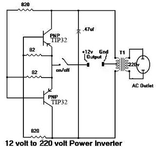
Simple Inverter with Two Transistors
The series below is a simple inverter circuit that will change the voltage of 12v dc to 220v ac, with use drive transistor 32 as its tip.
Inverter circuit is very simple and easy to assemble and is perfect for just starting to learn to assemble electronic circuits, you can use the transformer 2A to produce about 20 watts output. Do not forget to install coolers in its transistors. good luck.
Inverter circuit is very simple and easy to assemble and is perfect for just starting to learn to assemble electronic circuits, you can use the transformer 2A to produce about 20 watts output. Do not forget to install coolers in its transistors. good luck.
Sunday, March 17, 2013
Mini 50 Watt MOSFET Inverter Circuit
I have already discussed one 50 watt inverter circuit in one of my earlier posts, the only difference between the previous and the present design is in the output stage. The previous circuit involved power transistors where as here we have utilized mosfets making the configuration much easier and straightforward.
Rest of the stages are pretty much the same, in the earlier circuit we saw the involvement of a transistor based astable multivibrator for the generation of the required 50 Hz oscillations, here too we have incorporated a transitor operated AMV.
The earlier circuit had a couple of 2N3055 transistors at the output and as we all know driving power transistors efficiently requires proportionate amount of base drive, relative to the load current, because transistors depend on current drive rather than voltage drive, in contrast to mosfets.
Meaning, as the proposed load becomes higher, the base resistance of the relevant output transistor also gets dimensioned accordingly for enabling optimal amount of current to the base of the transistors,
Due to this obligation, in the previous design a additional driver stage had to be incorporated for facilitating better drive current to the 2N3055 transistors.
However when it comes to mosfets, this necessity becomes completely insignificant. As can be seen in the given diagram, the AMV stage is instantly preceded by the relevant gates of the mosfets, because mosfets have very high input resistance, which means the AMV transistors wouldnt be unnecessarily loaded and therefore the frequency from the AMVwouldnt be distorted due to the integration of the power devices.
The mosfets are alternately switched, which in turn switches the battery voltage/current inside the secondary winding of the transformer.
The output of the transformer gets saturated delivering the expected 220V to the connected loads.

Parts List
R1, R2 = 27K,
R3, R4, R5, R6 = 470 Ohms,
C1,C2 = 0.47uF/100V metallized
T1, T2 = BC547,
T3, T4 = any 30V, 10amp mosfet, N-channel.
Transformer = 9-0-9V, 8 amp
Battery = 12V,10AH
Rest of the stages are pretty much the same, in the earlier circuit we saw the involvement of a transistor based astable multivibrator for the generation of the required 50 Hz oscillations, here too we have incorporated a transitor operated AMV.
The earlier circuit had a couple of 2N3055 transistors at the output and as we all know driving power transistors efficiently requires proportionate amount of base drive, relative to the load current, because transistors depend on current drive rather than voltage drive, in contrast to mosfets.
Meaning, as the proposed load becomes higher, the base resistance of the relevant output transistor also gets dimensioned accordingly for enabling optimal amount of current to the base of the transistors,
Due to this obligation, in the previous design a additional driver stage had to be incorporated for facilitating better drive current to the 2N3055 transistors.
However when it comes to mosfets, this necessity becomes completely insignificant. As can be seen in the given diagram, the AMV stage is instantly preceded by the relevant gates of the mosfets, because mosfets have very high input resistance, which means the AMV transistors wouldnt be unnecessarily loaded and therefore the frequency from the AMVwouldnt be distorted due to the integration of the power devices.
The mosfets are alternately switched, which in turn switches the battery voltage/current inside the secondary winding of the transformer.
The output of the transformer gets saturated delivering the expected 220V to the connected loads.
Parts List
R1, R2 = 27K,
R3, R4, R5, R6 = 470 Ohms,
C1,C2 = 0.47uF/100V metallized
T1, T2 = BC547,
T3, T4 = any 30V, 10amp mosfet, N-channel.
Transformer = 9-0-9V, 8 amp
Battery = 12V,10AH
Subscribe to:
Posts (Atom)