Saturday, December 21, 2013
Simple LED Torch
A common problem with small torches is the short life-span both of the batteries and the bulb. The average incandescent torch, for instance, consumes around 2 Watts. The LED Torch in Fig. 1 consumes just 24 mW, giving it more than 80 times longer service from 4 AA alkaline batteries (that is, up to one months continuous service). Although the torchs light output is modest, it is nonetheless quite sufficient to illuminate a pathway for walking.
Circuit Diagram :

Fig. 1 : Simple LED Torch Circuit Diagram
The LED Torch is based on a 7555 timer running in astable mode (do not use an ordinary 555). A white LED (Maplin order code NR73) produces 400 mcd light output, which, when focussed, can illuminate objects at 30 metres. Try Conrad Electronic for what appears to be a stronger white LED (order code 15 37 45-11). A convex lens with short focal length is placed in front of the LED to focus the beam. If banding occurs at the beams perimeter, use another very short focal length lens directly in front of the LED to smooth the beam.
If a different supply voltage is preferred, the value of resistor R3 is modified as follows:
9V - 470 Ohm
12V - 560 Ohm
See my "Wind-up Torch" feature article in the October 2000 edition of Everyday Practical Electronics for a completely battery-free go-everywhere torch.

Thursday, December 19, 2013
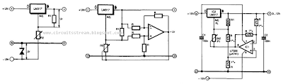
Simple But best Regulator Circuit Diagram
Tuesday, December 17, 2013
Watch Dog For Telephones
This little circuit keeps continuous watch over the telephone lines and sounds an alarm in case of any misuse. In addition it transmits a loud tone through the telephone lines to prevent further misuse. When switch S1 is turned on, the normal (on-hook) telephone line voltage at the output of bridge-rectifier diodes D1 to D4 is approximately 48 volts, which being well above the break-down voltage of zener diode D5, the diode conducts.

As a result transistor T2 gets forward biased. This effectively grounds the base of transistor T1 which is thus cut off and the remaining circuit does not get any power supply. In this state, only a small (negligible) current is taken by the circuit, which will not affect the telephone line condition. However, when handset of any telephone connected to the telephone lines is lifted (off-hook), line voltage suddenly drops to about 10 volts.
As a result, transistor T2 is switched off and transistor T1 gets forward biased via resistor R1. Now, the astable multivibrator built around timer IC1 starts oscillating and the speaker starts sounding. Output of the astable multivibrator is also connected to the base of transistor T1 through capacitor C5. As a result, only a loud (and irritating) tone is heard in the ear-piece of the unauthorized telephone instrument.
This circuit can be constructed on a veroboard using easily available low-cost components and it can be connected to any telephone line without the fear of malfunctioning. No extra power supply is required as it draws power from the telephone line for operation.
Note:
- Please disconnect the gadget when you are yourself using the telephone as it cannot distinguish between authorized and unauthorized operation.
Tuesday, October 8, 2013
Simple Transistor Tester
This is a simple circuit but we hope it will help you a lot and save your valuable time. You do not have to use millimeter to test a transistor if you build this circuit. You can have a 9 volts battery to operate the circuit. No matter if the transistor is NPN or PNP, if the transistor is shorted then no any LED should light. If the transistor is open Both the LED should light.
Now remember when you test a good PNP transistor then LED2 should light.
For NPN good transistor only LED1 should light.
Try to make the circuit on a PCB and put in a small box for its safety. Find a three pin socket and mounted it on the box. When you fix everything, only visible parts from the out side of the box should be the switch and three pins of the socket to test a transistor.

Sunday, October 6, 2013
Suzuki Swift 1997 Electrical Wiring Diagram
 |
| Suzuki Swift 1997 Electrical Wiring Diagram |
Friday, October 4, 2013
Pan Pot
 Series resistors R7 and R12 serve to ensure that the outputs can handle capacitive loads. Coupling capacitors C3, C6, and C9, may be omitted if an offset voltage of 20–30 mV is of no consequence in the relevant application. Capacitors C2, C5, and C8, ensure that the op amps remain stable even at unity gain. Capacitors C1, C4, and C7, minimize any r.f. interference, resulting in a usable bandwidth of 2.5 Hz to 200 kHz. The performance of the circuit is of sufficiently high quality to allow the pot being incorporated in good-quality control panels. Total harmonic distortion plus noise (THD+N) at a frequency of 1 kHz and a bandwidth of 22 kHz is 0.0014%. Over the band 20 Hz to 20 kHz and a bandwidth of 80 dB, this figure is still only 0.0023%. The circuit needs a power supply of ±18 V, from which it draws a current of about 16mA.
Wednesday, October 2, 2013
USB Powered PIC Programmer
