Thursday, December 19, 2013
Simple But best Regulator Circuit Diagram
This is the Simple But best Regulator Circuit Diagram.The best characteristic of this regulator is that the output voltage can be adjusted down to 0 V. The regulation is provided by an integrated regulator Type LM317. As is normal in supplies that can be adjusted to 0 V, this IC is used in conjunction with a zener diode. This diode provides a reference voltage that is equal, but of opposite sign, to the reference voltage (U,) of the regulator, as shown in Fig. 74-1 (a).
Potential divider R1/R2 enables the output voltage to be adjusted. In this circuit, the negative reference voltage is derived in a different manner: from the regulator with the aid of an op amp (Fig. 74-1 (b)). The op amp is connected as a differential amplifier that measures the voltage across Rl and inverts this voltage to Ur. An additional advantage of this method is that at low-output voltages, a change in the reference voltage has less effect on the output voltage than the circuit in Fig. 74-1 (a). The prototype, constructed as shown in Fig. 74-1 (c), gave very satisfactory results.
Regulator Circuit Diagram
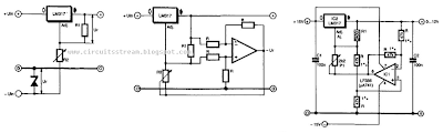
The op amp need not meet any special requirements: a 741 works fine, although an LF356 gives a slightly better performance. The negative supply for the op amp can be obtained with the aid of a center-tapped mains transformer.

Tuesday, December 17, 2013
Watch Dog For Telephones
Most of the telephone security devices available in market are simple but quite expensive. These devices provide blinking or beeping type line-tap/misuse indications. Quite often they do not offer guaranteed protection against unauthorized operation. A very simple and unique circuit of a telephone watch-dog to safeguard subscriber telephone lines against any fraud is described here.
This little circuit keeps continuous watch over the telephone lines and sounds an alarm in case of any misuse. In addition it transmits a loud tone through the telephone lines to prevent further misuse. When switch S1 is turned on, the normal (on-hook) telephone line voltage at the output of bridge-rectifier diodes D1 to D4 is approximately 48 volts, which being well above the break-down voltage of zener diode D5, the diode conducts.

As a result transistor T2 gets forward biased. This effectively grounds the base of transistor T1 which is thus cut off and the remaining circuit does not get any power supply. In this state, only a small (negligible) current is taken by the circuit, which will not affect the telephone line condition. However, when handset of any telephone connected to the telephone lines is lifted (off-hook), line voltage suddenly drops to about 10 volts.
As a result, transistor T2 is switched off and transistor T1 gets forward biased via resistor R1. Now, the astable multivibrator built around timer IC1 starts oscillating and the speaker starts sounding. Output of the astable multivibrator is also connected to the base of transistor T1 through capacitor C5. As a result, only a loud (and irritating) tone is heard in the ear-piece of the unauthorized telephone instrument.
This circuit can be constructed on a veroboard using easily available low-cost components and it can be connected to any telephone line without the fear of malfunctioning. No extra power supply is required as it draws power from the telephone line for operation.
Note:
Read More..
This little circuit keeps continuous watch over the telephone lines and sounds an alarm in case of any misuse. In addition it transmits a loud tone through the telephone lines to prevent further misuse. When switch S1 is turned on, the normal (on-hook) telephone line voltage at the output of bridge-rectifier diodes D1 to D4 is approximately 48 volts, which being well above the break-down voltage of zener diode D5, the diode conducts.

As a result transistor T2 gets forward biased. This effectively grounds the base of transistor T1 which is thus cut off and the remaining circuit does not get any power supply. In this state, only a small (negligible) current is taken by the circuit, which will not affect the telephone line condition. However, when handset of any telephone connected to the telephone lines is lifted (off-hook), line voltage suddenly drops to about 10 volts.
As a result, transistor T2 is switched off and transistor T1 gets forward biased via resistor R1. Now, the astable multivibrator built around timer IC1 starts oscillating and the speaker starts sounding. Output of the astable multivibrator is also connected to the base of transistor T1 through capacitor C5. As a result, only a loud (and irritating) tone is heard in the ear-piece of the unauthorized telephone instrument.
This circuit can be constructed on a veroboard using easily available low-cost components and it can be connected to any telephone line without the fear of malfunctioning. No extra power supply is required as it draws power from the telephone line for operation.
Note:
- Please disconnect the gadget when you are yourself using the telephone as it cannot distinguish between authorized and unauthorized operation.
Tuesday, October 8, 2013
Simple Transistor Tester
This is a simple circuit but we hope it will help you a lot and save your valuable time. You do not have to use millimeter to test a transistor if you build this circuit. You can have a 9 volts battery to operate the circuit. No matter if the transistor is NPN or PNP, if the transistor is shorted then no any LED should light. If the transistor is open Both the LED should light.
Now remember when you test a good PNP transistor then LED2 should light.
For NPN good transistor only LED1 should light.
Try to make the circuit on a PCB and put in a small box for its safety. Find a three pin socket and mounted it on the box. When you fix everything, only visible parts from the out side of the box should be the switch and three pins of the socket to test a transistor.

Sunday, October 6, 2013
Suzuki Swift 1997 Electrical Wiring Diagram
 |
| Suzuki Swift 1997 Electrical Wiring Diagram |
The Part of Suzuki Swift 1997 Electrical Wiring Diagram: computer data lines, cooling fan circuit,
defogger circuit, 1.3L engine performance circuit, horn circuit, instrument cluster circuit, interior light circuit, automatic transmission, power door lock circuit, radio circuits, power distribution circuit, shift interlock circuit, heater circuit, anti-lock brake circuits, Air back-up lamp circuit, exterior lamp circuit, warning system, wiper/washer circuit, ground distribution circuit, headlight circuit, conditioning circuit, charging circuit, starting circuit, supplemental restraint, etc. Features: assembly/dissasembly of the vehicle, to perform troubleshooting..Friday, October 4, 2013
Pan Pot
A pan pot enables a mono-phonic input signal to be positioned where desired between the stereo loudspeakers. When P1 (see diagram) is in the center position, there is no attenuation or amplification between the input and output. When the control is turned away from the center position, the signal in one channel will be amplified 3 dB more than the other. Circuit IC1 at the input is a buffer stage. It is arranged as an inverter to ensure that the phase of the input signal is identical to that of the output signal. The input impedance is set by R1 (10 kΩ). The output of the buffer is applied to stereo amplifiers IC2 and IC3. A special arrangement here is the positioning of P1, in conjunction with R3, R4, R8, and R9, in the feedback circuits of both amplifiers. This means that any adjustment of the potentiometer will have opposite effects in the amplifiers.
 Series resistors R7 and R12 serve to ensure that the outputs can handle capacitive loads. Coupling capacitors C3, C6, and C9, may be omitted if an offset voltage of 20–30 mV is of no consequence in the relevant application. Capacitors C2, C5, and C8, ensure that the op amps remain stable even at unity gain. Capacitors C1, C4, and C7, minimize any r.f. interference, resulting in a usable bandwidth of 2.5 Hz to 200 kHz. The performance of the circuit is of sufficiently high quality to allow the pot being incorporated in good-quality control panels. Total harmonic distortion plus noise (THD+N) at a frequency of 1 kHz and a bandwidth of 22 kHz is 0.0014%. Over the band 20 Hz to 20 kHz and a bandwidth of 80 dB, this figure is still only 0.0023%. The circuit needs a power supply of ±18 V, from which it draws a current of about 16mA.
Read More..
 Series resistors R7 and R12 serve to ensure that the outputs can handle capacitive loads. Coupling capacitors C3, C6, and C9, may be omitted if an offset voltage of 20–30 mV is of no consequence in the relevant application. Capacitors C2, C5, and C8, ensure that the op amps remain stable even at unity gain. Capacitors C1, C4, and C7, minimize any r.f. interference, resulting in a usable bandwidth of 2.5 Hz to 200 kHz. The performance of the circuit is of sufficiently high quality to allow the pot being incorporated in good-quality control panels. Total harmonic distortion plus noise (THD+N) at a frequency of 1 kHz and a bandwidth of 22 kHz is 0.0014%. Over the band 20 Hz to 20 kHz and a bandwidth of 80 dB, this figure is still only 0.0023%. The circuit needs a power supply of ±18 V, from which it draws a current of about 16mA.
Wednesday, October 2, 2013
USB Powered PIC Programmer
This simple circuit can be used to program the PIC16F84 and similar "flash memory" type parts. It uses a cheap 555 timer IC to generate the programming voltage from a +5V rail, allowing the circuit to be powered from a computer’s USB port. The 555 timer (IC1) is configured as a free-running oscillator, with a frequency of about 6.5kHz. The output of the timer drives four 100nF capacitors and 1N4148 diodes wir-ed in a Cockroft-Walton voltage multiplier configuration.
Circuit diagram:
The output of the multiplier is switched through to the MCLR/Vpp pin of the PIC during programming via a 4N28 optocoupler. Diodes ZD1 and D5 between the MCLR/Vpp pin and ground clamp the output of the multiplier to about 13.6V, ensuring that the maximum input voltage (Vihh) of the PIC is not exceeded. A 100kΩ resistor pulls the pin down to a valid logic low level (Vil) when the optocoupler is not conducting. The circuit is compatible with the popular "JDM" programmer, so can be used with supporting software such as "ICProg" (see http://www.ic-prog.com).
Author: Luke Weston - Copyright: Silicon Chip Electronics
Monday, September 30, 2013
Short Wave Monitor
This broadband AM receiver enables you to ‘monitor’ the shortwave radio band. The circuit has been deliberately designed to have low selectivity and is most sensitive in the range from 6 to 20 MHz. This frequency range contains most of the shortwave broadcast stations. In this configuration, whichever station has the strongest signal will be the easiest to hear. An interesting fact is that the signal strength of stations in this band changes quite a lot. This is because the ionosphere reflects the radio signals. Because this layer of the atmosphere is in constant motion, the received signal strengths from different directions are subject to continuous variation. During testing of our prototype Radio Netherlands World Service, Radio Finland and Deutsche Welle alternated as the strongest station at regular intervals.

This receiver not only gives a good indication of the myriad of stations on offer in the short-wave band but is also an excellent tool for monitoring the state of the ionosphere. The circuit actually consists of no more than an RF and an AF amplifier. The high-frequency amplification is carried out by the IF stage of a CA3089. This IC is actually intended for FM receivers, but the FM section is not used here. The internal level detector provides a signal of sufficient strength to drive an audio amplifier directly. An LM386 was selected for this task. This IC can directly drive an 8-Ω loudspeaker or headphones without any difficulty.
The power supply voltage is 9 V. Because of the modest power consumption a 9-V battery is very suitable. In addition, the circuit will work down to a voltage of about 5.5 V, so that the battery life will be extra long. The antenna will require a little experimentation. We obtained reasonable results with a piece of wire 50 cm long. A length of wire in the range of 5 to 15 meters should provide even better results at these frequencies.
Read More..

This receiver not only gives a good indication of the myriad of stations on offer in the short-wave band but is also an excellent tool for monitoring the state of the ionosphere. The circuit actually consists of no more than an RF and an AF amplifier. The high-frequency amplification is carried out by the IF stage of a CA3089. This IC is actually intended for FM receivers, but the FM section is not used here. The internal level detector provides a signal of sufficient strength to drive an audio amplifier directly. An LM386 was selected for this task. This IC can directly drive an 8-Ω loudspeaker or headphones without any difficulty.
The power supply voltage is 9 V. Because of the modest power consumption a 9-V battery is very suitable. In addition, the circuit will work down to a voltage of about 5.5 V, so that the battery life will be extra long. The antenna will require a little experimentation. We obtained reasonable results with a piece of wire 50 cm long. A length of wire in the range of 5 to 15 meters should provide even better results at these frequencies.
Subscribe to:
Posts (Atom)