Monday, September 30, 2013
Short Wave Monitor
This receiver not only gives a good indication of the myriad of stations on offer in the short-wave band but is also an excellent tool for monitoring the state of the ionosphere. The circuit actually consists of no more than an RF and an AF amplifier. The high-frequency amplification is carried out by the IF stage of a CA3089. This IC is actually intended for FM receivers, but the FM section is not used here. The internal level detector provides a signal of sufficient strength to drive an audio amplifier directly. An LM386 was selected for this task. This IC can directly drive an 8-Ω loudspeaker or headphones without any difficulty.
The power supply voltage is 9 V. Because of the modest power consumption a 9-V battery is very suitable. In addition, the circuit will work down to a voltage of about 5.5 V, so that the battery life will be extra long. The antenna will require a little experimentation. We obtained reasonable results with a piece of wire 50 cm long. A length of wire in the range of 5 to 15 meters should provide even better results at these frequencies.
Saturday, September 28, 2013
Crossover For Subwoofer
The crossover network is intended for use when an existing audio installation is to be extended by the addition of a subwoofer. Often, this additional loudspeaker is one that has been lying around for some time. If its frequency response extends down far enough, all is well and good, but a filter is then needed to cut off any frequencies above, say, 150 Hz. Often, a subwoofer network is an active filter, but here this would necessitate an additional power supply. The present network is a passive one, designed so that the speaker signal of the existing system can be used as the input signal.
Circuit diagram:
 Crossover Circuit Diagram For Subwoofer
Since the bass information is present in both (stereo) loudspeakers, the signal for the sub woofer can simply be tapped from one of them. The network is a 1st order low-pass filter with variable input (P1) and presettable cut-off frequency (P2). The signal from the loudspeaker is applied to terminal ‘LSP’. Voltage divider R1-R2-P1 is designed for use with the output signal of an average output amplifier of around d 50 W. The crossover frequency of the network may be varied between 50 Hz and 160 Hz with P2. The values of R3, P2, and C1, are calculated on the assumption that the subwoofer amplifier to be connected to K1 has a standard input resistance of 47 kΩ.
If this figure is lower, the value of C1 will need to be increased slightly. It is advisable to open the volume of the subwoofer amplifier fully and adjust the sound level with P1. This ensures that the input of the subwoofer amplifier cannot be overloaded or damaged. Make sure that the ground of the loudspeaker signal line is linked to the ground of the subwoofer amplifier. If phase reversal is required, this is best done by reversing the wires to the subwoofer. If notwithstanding the above additional protection is desired at the input of the subwoofer amplifier, this is best effected by ‘overload protection ’ elsewhere in this site.
Author: T. Giesberts Copyright: Elektor Electronics
Thursday, September 26, 2013
Float Charger For NiMH Cells
 Diode D1 protects the circuit against reverse polarity of the power supply and protects the LM317 should the power be disconnected while it is still connected to a charged battery pack. Resistor RCL and transistor Q1 limit the maximum current in the event of a short circuit or the connection of a severely discharged battery pack. LED2 provides an indication of voltage input to the charger. LED1 and the 680O resistor provide the same function for the charger output and also provide a minimum load for the regulator when the battery pack is nearing full charge. This is necessary to keep the regulator output from drifting up and damaging the batteries. The circuit uses an external DC plugpack and is suitable for four NiMH cells rated at 2.5Ah.
 Table 1 gives alternative values for 1-10 batteries in series at peak charge currents of between 200mA to 600mA. If you are using the specified plug-pack and the TO-220 packaged LM317T, you will need a heatsink rated at 12°C/W or better for any design other than the 200mA single cell charger. A TO-3 packaged device with the correct plug-pack will be OK without a heat-sink for any of the 200mA configurations and up to four cells charging at 400mA.
Tuesday, September 24, 2013
Modular Phono Preamplifier
High Quality Moving Magnet Pick-up module, Two-stage Series/Shunt feedback RIAA equalization
Any electronics amateur still in possess of a collection of vinyl recordings and aiming at a high quality reproduction should build this preamp and add it to the Modular Preamplifier chain. This circuit features a very high input overload capability, very low distortion and accurate reproduction of the RIAA equalization curve, thanks to a two-stage op-amp circuitry in which the RIAA equalization network was split in two halves: an input stage (IC1A) wired in a series feedback configuration, implementing the bass-boost part of the RIAA equalization curve and a second stage, implementing the treble-cut part of the curve by means of a second op-amp (IC2A) wired in the shunt feedback configuration.
This module comprises also an independent dual rail power supply identical to that described in the Modular Preamplifier Control Center. As with the other modules of this series, each electronic board can be fitted into a standard enclosure: Hammond extruded aluminum cases are well suited to host the boards of this preamp. In particular, the cases sized 16 x 10.3 x 5.3 cm or 22 x 10.3 x 5.3 cm have a very good look when stacked. See below an example of the possible arrangement of the rear panel of this module.
Circuit diagram :
 Modular Phono Preamplifier Circuit Diagram
Parts:
R1_____________270R 1/4W Resistor
R2_____________100K 1/4W Resistor
R3_____________2K2 1/4W Resistor
R4_____________39K 1/4W Resistor
R5_____________3K9 1/4W Resistor
R6_____________390K 1/4W Resistor
R7_____________33K 1/4W Resistor
R8_____________75K 1/4W Resistor (or two 150K resistors wired in parallel)
R9_____________560R 1/4W Resistor
C1_____________220pF 63V Polystyrene or Ceramic Capacitor
C2_____________1µF 63V Polyester Capacitor
C3_____________47µF 25V Electrolytic Capacitor
C4_____________10nF 63V Polyester Capacitor 5% tolerance or better
C5_____________1nF 63V Polyester Capacitor 5% tolerance or better
C6,C9__________100nF 63V Polyester Capacitors
C7,C10_________22µF 25V Electrolytic Capacitors
C8,C11_________2200µF 25V Electrolytic Capacitors
IC1____________LM833 or NE5532 Low noise Dual Op-amp
IC2____________TL072 Dual BIFET Op-Amp
IC3____________78L15 15V 100mA Positive Regulator IC
IC4____________79L15 15V 100mA Negative Regulator IC
D1,D2_________1N4002 200V 1A Diodes
J1,J2__________RCA audio input sockets
J3_____________Mini DC Power Socket
Notes:
- The circuit diagram shows the Left channel only and the power supply
- Some parts are in common to both channels and must not be doubled. These parts are: IC3, IC4, C6, C7, C8, C9, C10, C11, D1, D2 and J3.
- IC1 and IC2 are dual Op-Amps, therefore the second half of these devices will be used for the Right channel
- This module requires an external 15 - 18V ac (50mA minimum) Power Supply Adaptor.
Technical data:
Sensitivity @ 1KHz: 4.3mV RMS input for 200mV RMS output
Max. input voltage @ 100Hz: 53mV RMS
Max. input voltage @ 1KHz: 212mV RMS
Max. input voltage @ 10KHz: 477mV RMS
Frequency response @ 200mV RMS output: flat from 30Hz to 23KHz; -0.5dB @ 20Hz
Total harmonic distortion @ 1KHz and up to 8.8V RMS output: 0.0028%
Total harmonic distortion @10KHz and up to 4.4V RMS output: 0.008%
Source : www.redcircuits.com
Sunday, September 22, 2013
Steam Whistle
Friday, September 20, 2013
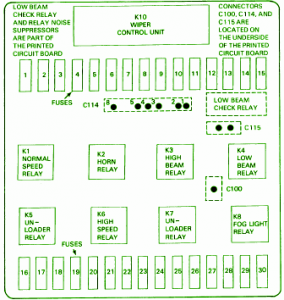
Fuse Box BMW 1992 325i Power Distribution Diagram
Fuse Box BMW 1992 325i Power Distribution Diagram
Fuse Panel Layout Diagram Parts: normal speed relay, horn relay, hhig beam relay, low beam relay, inloader relay, fog light relay.
Thursday, September 12, 2013
Tuesday, September 10, 2013
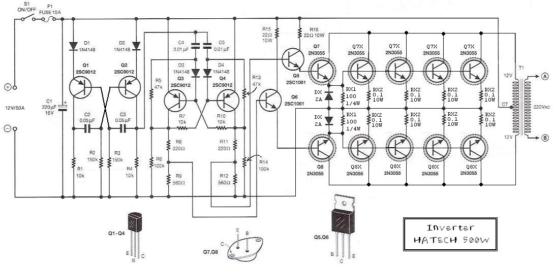
Simple 500W 12V to 220V Inverter


 Lub Oil Filter Arrangements Duplex