Sunday, March 31, 2013
1W BTL Audio Amplifier
The TDA8581(T) from Philips Semiconductors is a 1-watt Bridge Tied Load (BTL) audio power amplifier capable of delivering 1 watt output power into an 8-Wload at THD (total harmonic distortion) of 10% and using a 5V power supply.
The schematic shown here combines the functional diagram of the TDA8551 with its typical application circuit. The gain of the amplifier can be set by the digital volume control input. At the highest volume setting, the gain is 20 dB. Using the MODE pin the device can be switched to one of three modes: standby (MODE level between Vp and Vp–0.5 V), muted (MODE level between 1 V and Vp–1.4 V) or normal (MODE level less than 0.5 V). The TDA8551 is protected by an internal thermal shutdown protection mechanism. The total voltage loss for both MOS transistors in the complementary output stage is less than 1 V.
1 Watt BTL Audio Amplifier Circuit diagram:

Using a 5-V supply and an 8-W loudspeaker, an output power of 1 watt can be delivered. The volume control has an attenuation range of between 0 dB and 80 dB in 64 steps set by the 3-state level at the UP/DOWN pin: floating: volume remains unchanged; negative pulses: decrease volume; positive pulses: increase volume Each pulse at he Up/DOWN pin causes a change in gain of 80/64 = 1.25 dB (typical value).
When the supply voltage is first connected, the attenuator is set to 40 dB (low volume), so the gain of the total amplifier is then –20 dB. Some positive pulses have to be applied to the UP/DOWN pin to achieve listening volume. The graph shows the THD as a function of output power. The maximum quiescent current consumption of the amplifier is specified at 10 mA, to which should be added the current resulting from the output offset voltage divided by the load impedance.
Source : http://www.ecircuitslab.com/2011/05/1w-btl-audio-amplifier-circuit-diagram.html
Friday, March 29, 2013
Cable Wiring Diagram

Rj45 Ethernet Wiring How To.

Ethernet Cable Wiring Diagram Straight Lg.

Ethernet Straight Through Cable Pin Configuration.

Wireless Networks Vs Ethernet Networks Is There Still A Debate.

Ethernet Wiring Diagram Straight Thru Cable.

Ethernet Cable To Modem Router.

To How To Install An Ethernet Jack For A Home Network Part 1.

Gigabit Ethernet Uses Cable In The Same Way As 100base T Ethernet.
Cable Wiring Diagram.

Extra Costs For The Electricity And Telephone Network Voip Wiring.
Wednesday, March 27, 2013
Fuse Box Chevrolet Suburban 89 Diagram
Fuse Box Chevrolet Suburban 89 Diagram - Here are new post for Fuse Box Chevrolet Suburban 89 Diagram.


Fuse Panel Layout Diagram Parts: tailgate, power window, rear defogger, cruise control, diesel auxiliary fuel, tank selector switch, clock, cargo lamp, auto trans, auxiliary battery, rear defogger, rear heater, power locks.
Read More..
Fuse Box Chevrolet Suburban 89 Diagram


Fuse Panel Layout Diagram Parts: tailgate, power window, rear defogger, cruise control, diesel auxiliary fuel, tank selector switch, clock, cargo lamp, auto trans, auxiliary battery, rear defogger, rear heater, power locks.
Monday, March 25, 2013
Fuse Box Toyota 1995 Supra Left Kick Panel Diagram
Fuse Box Toyota 1995 Supra Left Kick Panel Diagram - Here are new post for Fuse Box Toyota 1995 Supra Left Kick Panel Diagram.


Fuse Panel Layout Diagram Parts: diode, engine room main wire,instrument panel, taillight relay, po main relay, defogger relay, medium current, noise filter, integration relay.
Read More..
Fuse Box Toyota 1995 Supra Left Kick Panel Diagram


Fuse Panel Layout Diagram Parts: diode, engine room main wire,instrument panel, taillight relay, po main relay, defogger relay, medium current, noise filter, integration relay.
Saturday, March 23, 2013
Large Blade Type Plug Wiring Diagram Gooseneck Lowboy

Band Graphic Equalizer Circuit Diagram Design Using Lmc835 Circuit.

Towing Trailer Wiring 7 Pin 7 Waycarend Jpg.

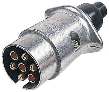
Pin Connector.

Tow Multi Pin Gm Ford Round To 4 Wire Flat 7 Pin Rv Trailer Wiring.

1997 2006 Jeep Wrangler 7 Pin To 4 Pin Adaptor 56019823.

Maybe You Could Just Replace The 6 Pin On The Trailer With A New Plug.
Way Plug Trailer End.

Hoppy 7 Pin Trailer Wiring Diagram Hoppy 7 Pin Trailer Wiring Diagram.

Large 7 Way Rv Blade Type Plug Wiring Diagram For Gooseneck Lowboy And.

Course The Colour Relate To The 7 Wiring Colours Of The Towing Loom.
Thursday, March 21, 2013
Trailer Wiring Connector Diagrams Conductor Plugs

Wiring Colors Http Www Tridenttrailers Com Trailer Wiring Diagram Htm.

Way Plug Trailer End.
Load Trail Trailer Wiring Plug Diagram.

2003 C240 Wire Color Codes For Trailer Wiring Install Justanswer.

Way 7 Pole Rv Travel Trailer Connector Wiring Color Code.

Pin S Type Caravan Wiring Uk Trailer Parts.
Pin Trailer Plug Wiring Pattern.

Trailer Wiring Connector Diagrams For 6 7 Conductor Plugs.

Typical 7 Way Trailer Wiring Diagram Circuit Schematic.

Towing And Trailers Ltd Worksop Trailer Plug 7 Pin N Type.
Tuesday, March 19, 2013
Flugzeugepiper Pa28 Airshampoo Aerodrome

Flugzeuge De Piper Saratoga Tc Ln Aaf.
Piper Cub Logo All Vector Logo.

Flugzeuge De Piper P28 T Cockpit Map.

Piper Pa 28 236 Dakota Role Civil Utility Aircraft Manufacturer Piper.

Flugzeuge De Piper Pa28 Im Airshampoo Aerodrome.

Flugzeuge De Piper Saratoga Tc Ln Aaf.

Aerostar Aircraft History Performance And Specifications.

Flugzeuge De Piper Saratoga Tc Ln Aaf.

This Aircraft Will Not Be Finished In The Traditional Cub Yellow But.

Flugzeuge De Piper Saratoga Tc Ln Aaf Cockpit.
Sunday, March 17, 2013
Mini 50 Watt MOSFET Inverter Circuit
I have already discussed one 50 watt inverter circuit in one of my earlier posts, the only difference between the previous and the present design is in the output stage. The previous circuit involved power transistors where as here we have utilized mosfets making the configuration much easier and straightforward.
Rest of the stages are pretty much the same, in the earlier circuit we saw the involvement of a transistor based astable multivibrator for the generation of the required 50 Hz oscillations, here too we have incorporated a transitor operated AMV.
The earlier circuit had a couple of 2N3055 transistors at the output and as we all know driving power transistors efficiently requires proportionate amount of base drive, relative to the load current, because transistors depend on current drive rather than voltage drive, in contrast to mosfets.
Meaning, as the proposed load becomes higher, the base resistance of the relevant output transistor also gets dimensioned accordingly for enabling optimal amount of current to the base of the transistors,
Due to this obligation, in the previous design a additional driver stage had to be incorporated for facilitating better drive current to the 2N3055 transistors.
However when it comes to mosfets, this necessity becomes completely insignificant. As can be seen in the given diagram, the AMV stage is instantly preceded by the relevant gates of the mosfets, because mosfets have very high input resistance, which means the AMV transistors wouldnt be unnecessarily loaded and therefore the frequency from the AMVwouldnt be distorted due to the integration of the power devices.
The mosfets are alternately switched, which in turn switches the battery voltage/current inside the secondary winding of the transformer.
The output of the transformer gets saturated delivering the expected 220V to the connected loads.

Parts List
R1, R2 = 27K,
R3, R4, R5, R6 = 470 Ohms,
C1,C2 = 0.47uF/100V metallized
T1, T2 = BC547,
T3, T4 = any 30V, 10amp mosfet, N-channel.
Transformer = 9-0-9V, 8 amp
Battery = 12V,10AH
Rest of the stages are pretty much the same, in the earlier circuit we saw the involvement of a transistor based astable multivibrator for the generation of the required 50 Hz oscillations, here too we have incorporated a transitor operated AMV.
The earlier circuit had a couple of 2N3055 transistors at the output and as we all know driving power transistors efficiently requires proportionate amount of base drive, relative to the load current, because transistors depend on current drive rather than voltage drive, in contrast to mosfets.
Meaning, as the proposed load becomes higher, the base resistance of the relevant output transistor also gets dimensioned accordingly for enabling optimal amount of current to the base of the transistors,
Due to this obligation, in the previous design a additional driver stage had to be incorporated for facilitating better drive current to the 2N3055 transistors.
However when it comes to mosfets, this necessity becomes completely insignificant. As can be seen in the given diagram, the AMV stage is instantly preceded by the relevant gates of the mosfets, because mosfets have very high input resistance, which means the AMV transistors wouldnt be unnecessarily loaded and therefore the frequency from the AMVwouldnt be distorted due to the integration of the power devices.
The mosfets are alternately switched, which in turn switches the battery voltage/current inside the secondary winding of the transformer.
The output of the transformer gets saturated delivering the expected 220V to the connected loads.
Parts List
R1, R2 = 27K,
R3, R4, R5, R6 = 470 Ohms,
C1,C2 = 0.47uF/100V metallized
T1, T2 = BC547,
T3, T4 = any 30V, 10amp mosfet, N-channel.
Transformer = 9-0-9V, 8 amp
Battery = 12V,10AH
Friday, March 15, 2013
How to Understand and Use white LEDs – Datasheet
White LEDs are the future lighting solutions for our cities and homes. They will be easily replacing the traditional CFL and other flurescent types of light producing devices. LEDs are extremely efficient when it comes to power consumption issues and are also highly durable and reliable with its specified features.
The invention of LED technology was a complete revelation, and it opened the doors to the researchers for exploring a whole new concept of lighting involving tiny devices which could produce immense illumination using very little electric power.

Today the concept may look old, yet still, LEDs especially white LED technology is improving at a very rapid pace. LED industry is surely growing and introducing advanced and more efficient versions of LEDs to us. Also these devices are getting very popular even with the common population and folks are seen using them and customizing them as per there own preferences.
Though white LEDs may look simple devices and illuminating them may not require more than a couple of pen light cells, white LEDs if not maintained or operated within a specific power range, might just fail in every respect.
Here we are going to discuss some of the basic tips regarding operating or illuminating these wonderful devices safely and optimally.
Before studying the above through a simple application circuit, it would be important to understand some of the following important specifications related to white LEDs.
In general most of the white LED types are specified with a maximum forward voltage drop of not more than 3.5 volts AC/DC.
Forward voltage drop means the maximum safe operating voltage of a particular LED at which the LED illuminates with maximum intensity without the danger of getting damaged.
The minimum current required by most white LED types at the above voltage is 10 mA, 20 mA being the optimal range, however these devices are able to operate even with 40 mA of current, producing dazzling brightness, almost at eye blinding levels.
Normal 5mm and 3mm types of white LEDs have two lead terminals, assigned as the cathode and the anode, or in layman’s words, a positive and a negative.
The cathode or the negative lead is relatively smaller in length than the anode or the positive lead and this also makes the terminals easily distinguishable.
For operating the device, the longer lead is connected to the positive while the smaller lead is connected with the negative of the power supply.
If the connected power to the LED is within the specified 3.5 volt range, then a series resistor may not be required to be connected with the LED.
However, if the supply voltage is more than the above limit, inclusion of a resistor becomes imperative.
Filing to do so may the burn the LED and damage it instantly.

The value of the of the resistor will depend on the magnitude of the applied voltage, and may be calculated using the following formula:
R = (Us – Fwd.)/I(current), where R is the resistance value which needs to be calculated, Us is the supply voltage, Fwd is the forward voltage drop of the LED and I is the current magnitude which is required to be supplied to the LED.
Suppose the supply voltage is 12, the forward voltage drop and the current as explained above are taken as 3.5 and 20 respectively, R may be calculated as:
R = (12 – 3.5)/0.02 = 425 Ohms.
In general the forward voltage drop of a particular LED becomes the important factor while issuing the operating input to the device, rest of the parameters ae not absolutely critical.
The forward voltage drop of an LED may be easily found out by connecting the particular device to a digital multimeter prods selected at the diode range.
The displayed figure directly provides the forward voltage range of the particular LED.
Subscribe to:
Posts (Atom)